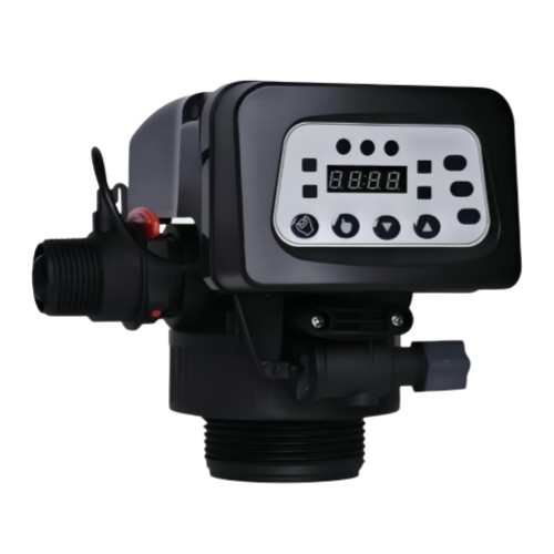
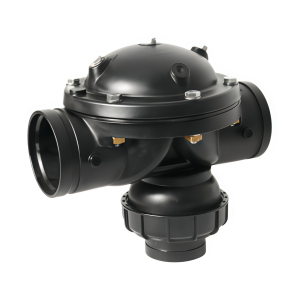
Custom Filter Control Valve Injection Molding Service / Control Valve Housings Molding
Processing Capabilities for Automatic Control Valve
| Item | Detailed Capabilities |
|---|---|
| Housing Material | PP, ABS, PC (UV-stabilized options available), Nylon (PA6/PA66), or custom engineering plastics |
| Seal Material | LSR (Liquid Silicone Rubber) Shore 50–60A |
| IP Protection Rating | IP65 (dust-tight & water jet resistant), IP68 (submersible, continuous immersion) |
| Welding Method | Ultrasonic welding, hot-plate welding, laser welding |
| Electronics Assembly | Insert molding, over-molding, or encapsulated PCB assembly for moisture protection |
| Pressure Rating | 0.15–1.0 MPa (1.5–10 bar), depending on valve design and material |
| Port / Connection | Threaded (BSP, NPT, Metric), socket weld, flange, union nut, or custom connections |
| Port Size | 1/2" to 2" (DN15–DN50), custom sizes available |
| Filter Compatibility | PP filter cartridges, pleated cartridges, mesh filter elements, or custom media |
| Operating Temperature | 5°C to 50°C (water), -10°C to 60°C (ambient), depending on material |
| Operating Voltage | 12V DC, 24V DC, 110V AC, 220V AC, or custom voltages |
| Display Type | LED digital display, LCD screen, or touch panel |
| Control Method | Manual, automatic (timer/volume), or programmable logic |
| Flow Rate | 0.5–5 m³/h (depending on port size and valve design) |
| Cycle Time | Adjustable regeneration cycles (1–99 days or 0.1–99.9 m³) |
| Color | Black, white, grey, blue, or custom colors matched to customer requirements |
| Surface Finish | Smooth, textured, or custom finishes available |
| Processing Tolerance | Diameter tolerance ±0.1mm, Thickness tolerance ±0.05mm |
| Certifications | ISO9001, ROHS, CE, UL, NSF, food-grade options available |
| Applications | Water softeners, RO systems, water filtration systems, irrigation, HVAC, and industrial fluid control |
Sealing Structure & Protection Design for Water-Contact Control Valve (IP65/IP68)
Because the control valve is in direct contact with water, it needs an IP65 or IP68 rating. Here is a breakdown of the sealing structure, protection design, processing techniques, difficulties, and countermeasures.
1. Interface Sealing Structure (Your First Line of Defense)
1) Welding Structure
- Ultrasonic welding for precise, localized melting of PP/ABS/PC housing joints.
- Hot-plate welding for larger, flat sealing surfaces with high bond strength.
- Laser welding for transparent or semi-transparent materials, offering minimal thermal stress.
- Weld parameters (frequency, amplitude, pressure, hold time) are optimized through DOE (Design of Experiments).
- Uneven weld lines due to inconsistent mating surface flatness.
- Material degradation from excessive heat input.
- Weak weld strength if contamination (oil, dust, moisture) is present at the joint.
- Maintain flatness tolerance < 0.05 mm on welding surfaces via CNC machining.
- Clean mating surfaces with plasma treatment or ultrasonic degreasing before welding.
- Use energy directors (triangular ridges) on the weld joint to concentrate ultrasonic energy and ensure uniform melting.
- Implement in-process weld monitoring (displacement, force, time) to detect defects.
2) Silicone Seal Ring Design
- LSR (Liquid Silicone Rubber) injection molding for precise, flash-free seals.
- Compression molding for larger or low-volume seal production.
- Over-molding directly onto the housing for integrated sealing.
- Inconsistent compression ratio leading to leakage or excessive deformation.
- Seal groove dimensions not matching LSR shrinkage.
- Seal displacement during assembly.
- Design groove dimensions with LSR shrinkage compensation (typically 2–4%).
- Maintain compression ratio of 20–30% by controlling groove depth and seal cross-section.
- Use assembly fixtures to keep the seal in place during housing closure.
- Verify sealing performance with air-decay leak testing at 1.5× rated pressure.
3) Button Sealing
- LSR injection molding for one-piece keypad with integrated sealing lips.
- Compression molding for custom keypad geometries.
- Over-molding of silicone onto the housing for permanent bonding.
- Poor adhesion between silicone keypad and housing.
- Button actuation force affected by seal compression.
- Wear or fatigue of silicone after repeated use.
- Use primer or plasma treatment to improve silicone-to-housing adhesion.
- Optimize keypad geometry (wall thickness, rib design) to balance sealing and tactile feel.
- Select high-tear-strength LSR (Shore 50–60A) for durability.
- Perform cycle testing (10,000+ actuations) to verify long-term sealing.
4) Display Sealing
- CNC machining of stepped groove for precise O-ring fit.
- O-ring compression molding with tight tolerance control.
- UV-resistant transparent window (PC or PMMA) bonded with adhesive or ultrasonic welding.
- Condensation inside the display due to temperature fluctuations.
- O-ring compression set over time.
- Window bonding failure or leakage.
- Use dual-seal design (O-ring + gasket) for redundant protection.
- Select low-compression-set O-ring material (e.g., LSR or FKM).
- Bond window with UV-curable adhesive or laser welding for a hermetic seal.
- Perform thermal cycling tests (-10°C to 60°C) to verify condensation resistance.
2. Cable and Connector Protection
Waterproof Cable & Rubber Seals
- Over-molding of rubber seals directly onto cable jackets.
- Insert molding of cable glands into the housing.
- Potting with epoxy or silicone for complete moisture blockage.
- Cable flexing causing seal fatigue or breakage.
- Incomplete sealing at cable entry point.
- Water ingress through stranded wire gaps.
- Use strain relief boots to prevent cable flexing at entry.
- Apply silicone potting compound inside the cable entry cavity.
- Use waterproof cable with individually sealed strands.
- Perform IP68 immersion testing (1m depth, 30 minutes) on finished assemblies.
3. Additional Protection Design Considerations
1) PCB Conformal Coating
- Processing Technique: Spray or dip coating with acrylic, silicone, or polyurethane.
- Difficulty: Coating thickness uniformity and coverage under components.
- Countermeasure: Use automated spray coating with UV inspection; properly mask connectors.
2) Gasket Design for Housing Joints
- Processing Technique: Die-cut or molded gaskets from EPDM, NBR, or LSR.
- Difficulty: Compression set and creep over time.
- Countermeasure: Use low-compression-set materials; design groove depth to maintain 20–30% compression.
3) Venting & Pressure Equalization
- Processing Technique: Install Gore-Tex or ePTFE vent membranes.
- Difficulty: Membrane blockage or damage.
- Countermeasure: Use a hydrophobic vent membrane with an IP68 rating; protect with a cover.
Our Workflow
A transparent, step-by-step process from design to delivery — tailored for automatic control valves.
Stage 1: R&D Support
We support customer R&D for automatic control valve applications. Create the files or improve the design if needed (UG, SolidWorks, ProE, AutoCAD, etc.). We help optimize valve body geometry, port size, thread type, union nut design, sealing structure (O-ring grooves, LSR seals), electronics housing design, button and display layout, and IP protection strategy for your specific water control requirements.
Stage 2: Mold Process
Mold design (DFM report) → check/approve → approved → make mold → produce sample → sample confirmed → check final mold quality ready to export.
Includes main body mold, top cover mold, bottom housing mold, union nut mold, thread inserts, slider mechanisms, button keypad mold, and display window mold design.
Stage 3: Sample Modification
If the first sample does not meet the customer's requirements (e.g., pressure rating, thread fit, sealing performance, IP protection level, button actuation, or fit clearance with union nuts), we can modify the mold to meet them.
Stage 4: Sample Delivery
Produce the customer's requested quantity of automatic control valve samples, with free shipping.
Stage 5: Final Delivery
Deliver goods by sea or air; we can accommodate special requirements based on customer demands.
Packaging options are available to protect valves from damage, deformation, and contamination during transport.
Why Choose Yixing Technology?
Partner with a trusted leader in precision automatic control valve manufacturing.
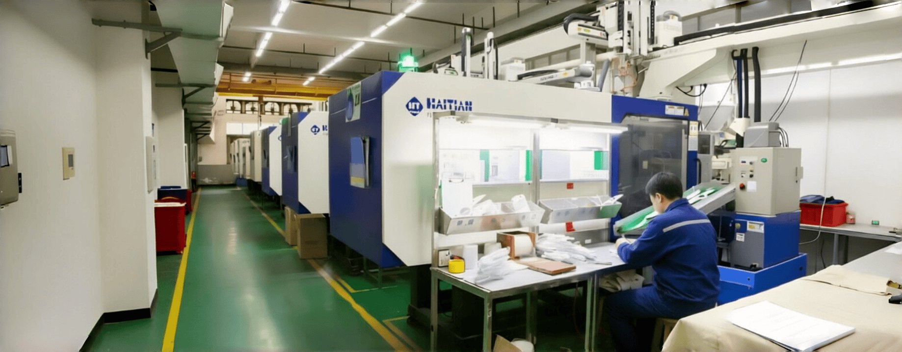
We have successfully produced more than 1500 new injection molds and parts since 2006.
Extensive experience in molding valve bodies, top covers, bottom housings, threaded union nuts, transparent components, and assembling complete control valves with integrated electronics and sealing systems.Strict quality control system, providing ROHS/CE certification for your peace of mind.
We inspect each automatic control valve batch for dimensional accuracy, thread quality, pressure resistance, sealing performance, IP protection rating, button function, display clarity, and fit clearance with union nuts.We provide more value-added operations to simplify your supply chain from design to delivery.
From housing injection molding and thread forming to LSR seal over-molding, ultrasonic welding, electronics assembly, pressure testing, IP testing, and global shipping — all under one roof.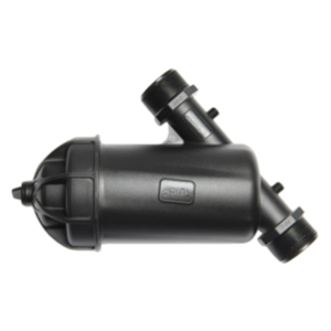
Start Your Quote Here
CATEGORIES
LATEST NEWS
CONTACT US
- Mobile: +8615000908770
- Tel: +86-21-51662821
- WhatsApp: 8615000908770
- Email: contact@yxplasticmolding.com
- Address: Room 323, Building B, Hongchun Business Park, No. 980 Qinghewan Road, Qingpu District, Shanghai