Custom Filter Element Manufacturing / Mesh Insert Molding Services
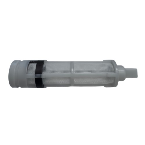
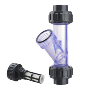
Processing Capabilities for Inline Mesh Filter Cartridge
| Item | Detailed Capabilities |
|---|---|
| Material (Housing) | Nylon (PA6/PA66), PP, PVC, CPVC, PVDF, ABS, PC (Polycarbonate), or custom engineering plastics |
| Material (Filter Element) | Nylon mesh, black wire cloth, PP mesh, PET mesh, stainless steel wire cloth |
| Housing Style | Inline / Cylindrical / Cartridge-style / Straight-through |
| Transparent Housing | PC, PMMA (Acrylic), or clear Nylon for visual flow monitoring and filter condition inspection |
| Disc Diameter | 5–500 mm (custom sizes available) |
| Cartridge Outer Diameter | 20–150 mm (custom sizes available) |
| Cartridge Length | 50–500 mm (custom lengths available) |
| Shapes | Cylindrical, pleated, multi-layered, conical, or fully custom designs |
| Mesh Count | 10–500 meshes (plain weave, twill weave, or dutch weave) |
| Filtration Accuracy | 50–1000 μm (nominal or absolute rating) |
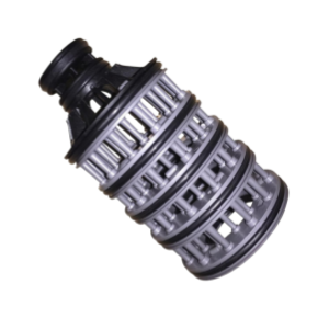
| Structure | Single layer, multiple layers, or composite structures with inner core and outer mesh sleeve |
| Frame Style | Over molding (encapsulation), insert molding, ultrasonic welding, heat staking, or snap-fit assembly |
| Connection Types | Threaded (BSP, NPT, Metric), hose barb, push-fit, socket weld, flange, or custom connections |
| Port Size | 1/4" to 2" (DN8–DN50), custom sizes available |
| Pressure Rating | 0.6–1.6 MPa (6–16 bar), depending on material and design |
| Temperature Range | -20°C to 120°C (depending on housing material) |
| Sealing Method | O-ring, gasket, integrated over-molded seal, or black retaining ring compression seal |
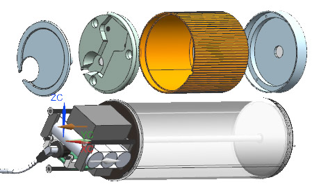
| Assembly | Complete inline filter cartridge assembly including transparent housing, mesh sleeve, end caps, retaining ring, and seals |
| Surface Finish | Smooth, textured, or custom finishes available |
| Color | Black, white, grey, blue, clear, or custom colors matched to customer requirements |
| Processing Tolerance | Diameter tolerance ±0.1mm, Length tolerance ±0.5mm |
| Certifications | ISO9001, ROHS, CE, food-grade options available |
| Applications | Water treatment, RO pre-filtration, irrigation, chemical processing, HVAC, marine, aquarium, and industrial fluid filtration |
Processing Techniques & Difficulties for Semi-Transparent SCR Filter Cartridge
1. Thin-Walled, Long Tubular Shape
Key Point:
The thin-walled, long tubular shape makes it prone to short shots or warping. So we need high-speed, high-pressure injection combined with precise mold temperature control, plus a hot runner system to make sure the melt fills the cavity evenly.
Processing Techniques:
- Hot runner system with valve gates for precise filling control and reduced material waste.
- High-speed injection (200–500 mm/s) to fill thin walls before the melt freezes.
- High injection pressure (120–180 MPa) to overcome high flow resistance in long, thin sections.
- Multi-stage injection profile to balance flow front velocity and avoid jetting.
- Precise mold temperature control (80–120°C depending on material) using oil or pressurized water heaters.
- CAE flow simulation (Moldflow) to optimize gate location, runner size, and filling balance.
- Conformal cooling channels for uniform temperature distribution along the tubular length.
Difficulties:
- Short shots at the far end of the tube due to premature melt freezing.
- Warpage along the length due to uneven cooling and packing.
- Weld lines where flow fronts meet, reducing transparency and strength.
- High scrap rate during startup due to unstable filling.
Countermeasures:
- Use high melt temperature (240–280°C for PA/PC, 220–250°C for PP) to improve flowability.
- Increase injection speed and packing pressure (85–95% of injection pressure) with a long hold time.
- Optimize gate location to balance flow length and avoid weld lines in critical areas.
- Use hot runner with sequential valve gating to control fill sequence and weld line location.
- Implement scientific molding (decoupled molding) to determine optimal switchover point.
- Use mold temperature controllers with PID feedback to maintain ±1°C uniformity.
- Anneal parts after molding (80–100°C, 2–4 hours) to relieve internal stress and reduce warpage.
2. Metal Mesh Over-Molding
Key Point:
Metal mesh over-molding. Positioning is tricky: the mold must be designed to place the mesh during injection.
Processing Techniques:
- Insert molding with a precision mesh positioning jig to hold the mesh in place during injection.
- Magnetic or vacuum fixturing to secure the mesh without damaging it.
- Over-molding with molten polymer encapsulating the mesh edges for a leak-proof bond.
- Mesh pre-forming (cutting, rolling, or pleating) to match the cavity geometry.
- Plasma treatment on the mesh surface to improve polymer adhesion.
- Pre-heating the mesh (80–120°C) to improve bonding and reduce thermal shock.
Difficulties:
- Mesh displacement during injection due to high melt pressure.
- Incomplete encapsulation causing bypass leakage.
- Mesh damage (tearing, deformation) during mold closing or injection.
- Weak bond between mesh and polymer leading to delamination.
- Mesh edges creating flow obstruction and weld lines.
Countermeasures:
- Use mesh positioning jigs with tight tolerances (±0.05mm) to hold the mesh securely.
- Design mechanical anchors (grooves, ribs, or perforations) on the mesh edge for polymer interlocking.
- Reduce injection speed locally around the mesh to prevent displacement.
- Use low-viscosity polymer grades to improve penetration into mesh openings.
- Pre-dry the mesh to remove moisture and prevent steam pockets.
- Inspect mesh position in-process using vision systems or sensors.
- Perform pressure testing on 100% of parts to detect bypass leakage.
3. Injection Gate Location & Ejection
Key Point:
Injection gate location. Ejection is a headache – it's easy to end up with drag marks or stress whitening. We recommend a gentle ejection system, like stripper sleeves or air-assisted ejection, along with proper draft angles and a mirror-polished cavity surface.
Processing Techniques:
- Gate location optimization using CAE simulation to balance flow and minimize weld lines.
- Hot runner valve gates for precise fill control and reduced gate vestige.
- Stripper sleeves for uniform ejection force around the cylindrical part.
- Air-assisted ejection for gentle release of thin-walled sections.
- Mirror-polished cavity (SPI A1–A2) to reduce friction during ejection.
- Proper draft angles (1.5–3°) on all vertical surfaces.
- Ejection simulation to predict stress points and optimize ejection pin layout.
Difficulties:
- Drag marks on the transparent surface during ejection.
- Stress whitening (crazing) from excessive ejection force.
- Part deformation or cracking during ejection.
- Gate vestige affecting appearance and flow characteristics.
- Ejection marks on sealing surfaces causing leakage.
Countermeasures:
- Use stripper sleeves instead of ejector pins for uniform force distribution.
- Apply air-assisted ejection for thin-walled or delicate sections.
- Polish cavity surfaces to SPI A1–A2 finish to minimize friction.
- Maintain draft angles of 1.5–3° on all vertical walls.
- Use mold release agent sparingly (or not at all for transparent parts).
- Optimize ejection speed and force using servo-controlled ejection.
- Anneal parts after molding to relieve stress and prevent stress whitening.
- Inspect for drag marks and stress whitening under polarized light.
4. Transparency & Surface Quality
Key Point:
Semi-transparent parts require high surface quality and consistent optical properties. Any flow marks, weld lines, or contamination will affect appearance and function.
Processing Techniques:
- Use high-purity, optical-grade resins with a consistent melt flow index.
- Mirror-polish mold surfaces to SPI A1–A2.
- High mold temperature to improve surface replication and reduce flow marks.
- Slow injection speed near the gate to avoid jetting and flow marks.
- Vacuum venting to prevent gas entrapment and surface defects.
- Clean room assembly to prevent contamination.
Difficulties:
- Flow marks and weld lines reducing transparency.
- Sink marks on thick sections.
- Contamination (dust, oil) causing surface defects.
- Color variation between batches.
Countermeasures:
- Optimize injection speed profile to maintain uniform flow front.
- Use sequential valve gating to control weld line location.
- Maintain consistent mold temperature (±1°C) across all cavities.
- Use vacuum venting or porous vent inserts to eliminate gas traps.
- Handle materials in closed-loop conveying systems to prevent contamination.
- Use color masterbatch with tight tolerance and consistent dispersion.
- Perform visual inspection under controlled lighting for surface defects.
5. Dimensional Accuracy & Fit
Key Point:
The part must fit precisely into the SCR system housing, with tight tolerances on the outer diameter, length, and connection features.
Processing Techniques:
- CNC-machined mold inserts for tight tolerances (±0.05mm).
- In-process gauging for critical dimensions.
- Statistical process control (SPC) for dimensional trends.
- Annealing to stabilize dimensions after molding.
Difficulties:
- Shrinkage variation causing dimensional deviation.
- Warpage affecting fit and sealing.
- Batch-to-batch variation in material shrinkage.
Countermeasures:
- Use CAE shrinkage simulation to compensate mold dimensions.
- Maintain consistent mold temperature and packing pressure.
- Anneal parts (80–100°C, 2–4 hours) to stabilize dimensions.
- Implement SPC with control charts for critical dimensions.
- Inspect 100% of parts for fit-critical dimensions using automated vision systems.
Our Workflow
A transparent, step-by-step process from design to delivery — tailored for inline mesh filter cartridges.
Stage 1 — Inquiry & Drawing Review
You send us your drawing or sample. We review dimensions, material requirements, wall thickness, mesh specifications, and SCR system compatibility within 24 hours.
Stage 2 — DFM Report
Our engineers provide a Design-for-Manufacturability report, highlighting potential issues such as short shots, warpage, mesh displacement, and ejection marks, and suggesting optimizations for moldability, transparency, and cost.
Stage 3 — Mold Design & Fabrication
We design the mold in SolidWorks, simulate filling and cooling with Moldflow, and machine the mold in-house with hot runner systems, mesh positioning jigs, and conformal cooling channels (lead time: 25–35 days).
Stage 4 — Sampling & Approval
We produce T1 samples with over-molded metal mesh, send them with inspection reports (dimensional, mesh pull-test, leak-test, transparency inspection), and iterate until you approve.
Stage 5 — Mass Production & Shipping
Once approved, we begin mass production with full SPC monitoring, 100% pressure testing, and cold cycling verification. Typical lead time: 15–20 days after approval.
Why Choose Yixing Technology?
Partner with a trusted leader in precision mesh insert molding for filter elements.
20+ Years Experience
Specialized in over-molding and insert molding since 2003. We have completed 5,000+ custom filter disc and cartridge projects.
Extensive experience in over-molding metal mesh, black wire cloth, and engineering plastics for automotive SCR systems.
ISO 9001:2015 Certified
Full quality management system with traceable production records for every batch.
We inspect each SCR filter cartridge batch for dimensional accuracy, mesh bonding strength, leak-proof performance, transparency, and low-temperature impact resistance.
One-Stop Service
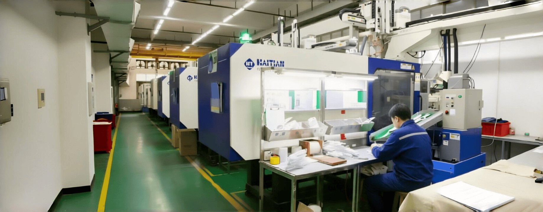
From mesh sourcing → mold design → injection molding → assembly → packaging, all under one roof in our Shanghai factory.
From semi-transparent housing molding and metal mesh over-molding to annealing, pressure testing, and global shipping — all under one roof.
Start Your Quote Here
CATEGORIES
LATEST NEWS
CONTACT US
- Mobile: +8615000908770
- Tel: +86-21-51662821
- WhatsApp: 8615000908770
- Email: contact@yxplasticmolding.com
- Address: Room 323, Building B, Hongchun Business Park, No. 980 Qinghewan Road, Qingpu District, Shanghai