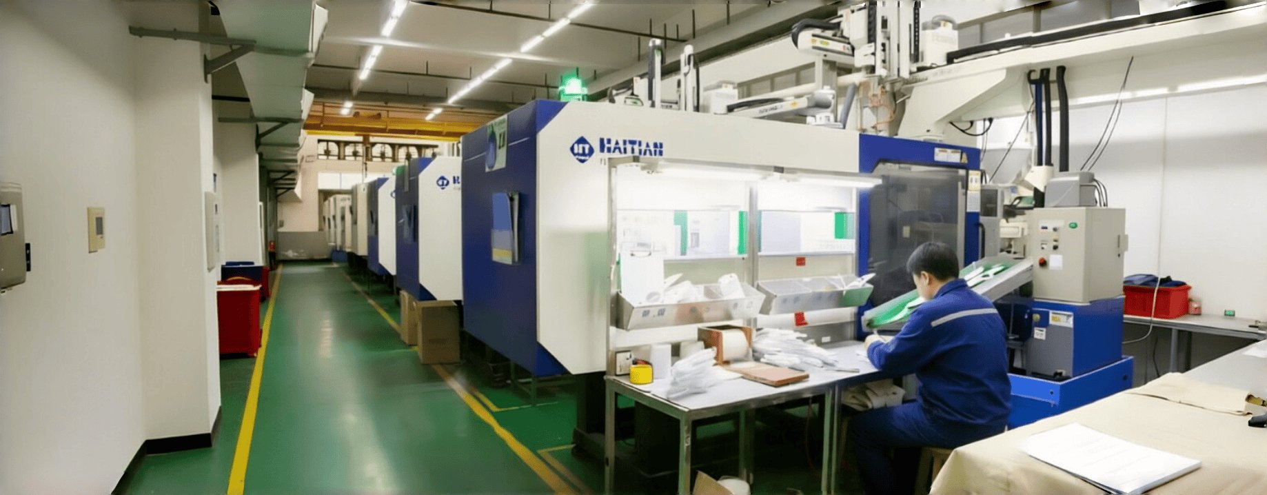
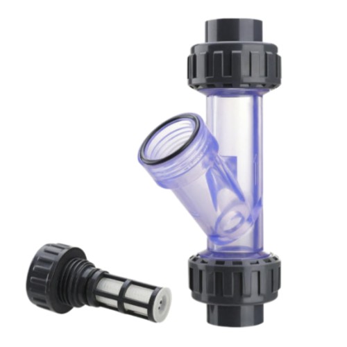
Three-way Filter Housing with Union Nuts by Injection Molding
Processing Capabilities for Three-way Filter Housing
| Item | Detailed Capabilities |
|---|---|
| Material (Housing) | Nylon (PA6/PA66), PP, PVC, CPVC, PVDF, ABS, PC (Polycarbonate), or custom engineering plastics |
| Material (Filter Element) | Nylon mesh, black wire cloth, PP mesh, PET mesh, stainless steel wire cloth |
| Housing Style | Three-way / Y-type / Angle-type / Inline / T-type |
| Transparent Housing | PC, PMMA (Acrylic), or clear Nylon for visual flow monitoring |
| Disc Diameter | 5–500 mm (custom sizes available) |
| Shapes | Square, rectangular, round, oval, annular, kidney shape, fan-shaped, and fully custom designs |
| Mesh Count | 10–500 meshes (plain weave, twill weave, or dutch weave) |
| Filtration Accuracy | 50–1000 μm (nominal or absolute rating) |
| Frame Style | Over molding (encapsulation), insert molding, ultrasonic welding, or heat staking |
| Connection Types | Threaded (BSP, NPT, Metric), socket weld, flange, hose barb, or custom connections |
| Port Size | 1/4" to 4" (DN8–DN100), custom sizes available |
| Pressure Rating | 0.6–1.6 MPa (6–16 bar), depending on material and design |
| Temperature Range | -40°C to 120°C (depending on housing material) |
| Sealing Method | O-ring, gasket, or integrated over-molded seal |
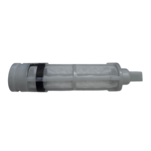
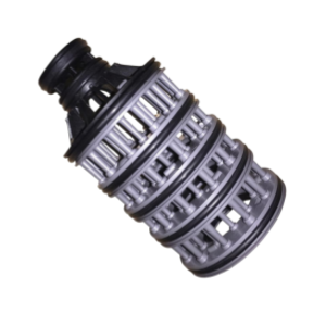
| Assembly | Complete three-way filter housing assembly including body, caps, mesh filter element, and seals |
| Surface Finish | Smooth, textured, or custom finishes available |
| Color | Black, white, grey, blue, clear, or custom colors matched to customer requirements |
| Processing Tolerance | Diameter tolerance ±0.1mm, Thickness tolerance ±0.05mm |
| Certifications | ISO9001, ROHS, CE, food-grade options available |
| Applications | Water treatment, irrigation, chemical processing, HVAC, marine, aquarium, and industrial fluid filtration |
Injection Molding Difficult Points & Processing Techniques for Three-way Filter Housing
1. Mold Structure Design
1) Parting Line and Slider Design
Key Point:
Try to keep sealing surfaces (like O-ring grooves or tapered faces) off the slider parting lines. Ideally, put them on the main parting line on the fixed or moving side to improve concentricity and surface finish.
The main body is Y-shaped, so you'll need split sliders (lifters) to form the side outlets. The sliders need wear plates and angle pins to make sure they open and close smoothly.
Additional Processing Techniques:
- Use CNC machining to precisely cut the slider tracks and angle pin holes, ensuring smooth movement and minimal wear.
- Apply surface polishing (SPI A1–A3 finish) to all sealing surfaces to reduce friction and improve sealing performance.
- For high-volume production, use hardened steel inserts (HRC 48–52) for sliders and wear plates to extend mold life.
2) Thread Forming Method
Key Point:
The big threads on the union nuts are usually unscrewed automatically using a hydraulic motor-driven unscrewing mechanism. For small quantities, we can use threaded inserts and manually unscrew them to save on tooling costs. For high-volume production, make sure the unscrewing speed stays perfectly synced with the mold opening to avoid scratching the threads.
Additional Processing Techniques:
- Use CNC-machined thread inserts with precise pitch and profile to ensure smooth thread forming.
- For automated unscrewing, program the hydraulic motor speed to match the mold opening stroke using a servo-controlled system.
- Apply thread polishing after molding to remove minor scratches and improve thread engagement.
- Implement in-process thread gauging (GO/NO-GO gauges) to verify thread dimensions every 500 shots.
3) Cooling System Design
Key Point:
For the thick sections—like the junction in the center—use beryllium-copper inserts with straight cooling lines to speed up heat dissipation. This minimizes warpage from uneven thermal stress and makes sure the body doesn't bend and throw the two end ports out of alignment.
The three-way geometry has uneven wall thickness—thick at the joints and thin on the pipe walls. So a reasonable cooling system design is needed.
Additional Processing Techniques:
- Use CAE cooling simulation (e.g., Moldflow) to optimize cooling channel layout and predict temperature distribution.
- Implement baffled or bubbler cooling for deep cores and complex geometries to ensure uniform cooling.
- Use beryllium-copper inserts (BeCu) for high-heat areas; these conduct heat 3–5 times faster than steel.
- Consider conformal cooling channels (3D-printed mold inserts) for the Y-junction to achieve uniform cooling and reduce cycle time.
- Monitor mold temperature continuously with thermocouples and adjust flow rates accordingly.
2. Injection Molding Process Control
1) Switchover Point and Multi-stage Packing
Key Point:
You'll need high packing pressure—usually 80%–90% of injection pressure—and a long packing time. Then lower the pressure and hold longer to relieve internal stress and prevent warpage down the road.
The union nut areas are pretty thick, so they're prone to sink marks.
Additional Processing Techniques:
- Use scientific molding (decoupled molding) to determine the exact switchover point from velocity control to pressure control.
- Implement multi-stage packing profiles: Stage 1: High pressure (80–90%) for initial packing; Stage 2: Medium pressure (50–60%) for compensation; Stage 3: Low pressure (20–30%) for stress relief.
- Use gate seal analysis to determine optimal hold time and prevent backflow.
- For thick union nut areas, use localized cooling or post-mold cooling fixtures to prevent sink marks.
2) Melt Temperature and Mold Temperature
Key Point:
Keep the mold temperature consistent across the sealing surfaces—around 40–60°C is a good range—this can avoid weak weld lines or undersized dimensions from localized overcooling.
Materials like PP are temperature-sensitive. We need to set up zone-by-zone barrel temperatures to avoid overheating and degradation.
Additional Processing Techniques:
- Use infrared thermography to verify uniform mold surface temperature before production.
- Implement zone-by-zone barrel temperature control with separate PID controllers for each heating zone.
- For PP, maintain melt temperature between 200–230°C; for PA6/PA66, 240–280°C.
- Use hot runner systems with independent temperature control for each gate to ensure balanced filling.
- Purge the barrel regularly to prevent material degradation and contamination.
3. Post-processing and Inspection
1) Annealing for Stress Relief
Key Point:
After molding, it's a good idea to put the parts in an oven at 60–80°C for about 1–2 hours to let the residual stress relax. This helps prevent creep over time and potential leaks later on.
Additional Processing Techniques:
- Use controlled-rate annealing (slow heating and cooling) to prevent thermal shock and new stress formation.
- For PA6/PA66, anneal at 80–100°C for 2–4 hours for optimal stress relief.
- Use fixture annealing (holding parts in a jig during cooling) to maintain dimensional stability.
- Verify stress relief using polarized light inspection or solvent stress testing.
2) Pressure Test
Key Point:
Set up a test fixture, install the nuts and seals, then perform the pressure test to check the leak rate. This catches out-of-tolerance parts before they ship.
Additional Processing Techniques:
- Use automated pressure test stations with programmable pressure ramp and hold cycles.
- Test at 1.5× rated pressure for 30–60 seconds to ensure a safety margin.
- Use air-decay leak testing or water immersion testing depending on customer requirements.
- Record and trace test results for each batch; implement statistical process control (SPC) for leak rate.
- For critical applications, perform burst pressure testing on sample parts to verify ultimate strength.
4. Other Processing Techniques
1) Material Drying & Handling
- Pre-dry PP at 80–100°C for 2–4 hours; PA6/PA66 at 80–120°C for 4–6 hours.
- Use desiccant dryers with dew point monitoring to ensure moisture content <0.05%.
- Handle dried material in closed-loop conveying systems to prevent re-absorption of moisture.
2) Gate & Runner Design
- Use balanced runner systems to ensure uniform filling of all three ports.
- For Y-shaped bodies, use sequential valve gating to control weld line location and improve strength.
- Design full-round runners with adequate diameter to minimize pressure drop.
3) Ejection System Design
- Use stripper plates or air ejection for thin-walled sections to prevent deformation.
- For threaded caps, use unscrewing ejection synchronized with mold opening.
- Ensure uniform ejection force across all part surfaces to prevent warping.
4) Surface Finishing & Post-Mold Operations
- Deflashing: Use cryogenic or manual deflashing for precision threads and sealing surfaces.
- Polishing: Polish transparent housings to optical clarity (SPI A1–A2).
- Assembly: Install O-rings, seals, and filter mesh in a clean environment to prevent contamination.
5) Quality Control & Traceability
- Implement in-process inspection at critical stages: after molding, after annealing, and after assembly.
- Use vision systems for dimensional verification of threads and sealing surfaces.
- Maintain batch traceability with material lot numbers, mold cavity numbers, and process parameters.
- Provide inspection reports (dimensional, pressure, filtration) with each shipment.
Our Workflow
A transparent, step-by-step process from design to delivery — tailored for three-way filter housings.
Stage 1: R&D Support
We support customer R&D for three-way filter housing applications. Create the files or improve the design if needed (UG, SolidWorks, ProE, AutoCAD, etc.). We help optimize housing geometry, Y-junction structure, port size, thread type, union nut design, mesh selection (mesh count, wire diameter, material), and sealing design for your specific fluid filtration requirements.
Stage 2: Mold Process
Mold design (DFM report) → check/approve → approved → make mold → produce sample → sample confirmed → check final mold quality ready to export.
Includes main body mold, union nut mold, thread inserts, slider mechanisms, and mesh cutting die design.
Stage 3: Sample Modification
If the first sample does not meet the customer's requirements (e.g., pressure rating, thread fit, sealing performance, filtration accuracy, or fit clearance with union nuts), we can modify the mold to meet them.
Stage 4: Sample Delivery
Produce the customer's requested quantity of three-way filter housing samples, with free shipping.
Stage 5: Final Delivery
Deliver goods by sea or air; we can accommodate special requirements based on customer demands.
Packaging options are available to protect housings from damage, deformation, and contamination during transport.
Why Choose Yixing Technology?
Partner with a trusted leader in precision three-way filter housing manufacturing.
20+ Years Experience
We have successfully produced more than 1500 new injection molds and parts since 2006.
Extensive experience in molding Y-shaped housings, threaded union nuts, transparent bodies, and assembling complete three-way filter housings with mesh filter elements.
ISO9001 Certificated
Strict quality control system, providing ROHS/CE certification for your peace of mind.
We inspect each three-way filter housing batch for dimensional accuracy, thread quality, pressure resistance, sealing performance, fit clearance with union nuts, and filtration efficiency.
One Stop Service
We provide more value-added operations to simplify your supply chain from design to delivery.
From housing injection molding and thread forming to mesh die-cutting, over-molding, assembly, pressure testing, and global shipping — all under one roof.
Start Your Quote Here
CATEGORIES
LATEST NEWS
CONTACT US
- Mobile: +8615000908770
- Tel: +86-21-51662821
- WhatsApp: 8615000908770
- Email: contact@yxplasticmolding.com
- Address: Room 323, Building B, Hongchun Business Park, No. 980 Qinghewan Road, Qingpu District, Shanghai