Multi-Cavity PEEK Injection Molding
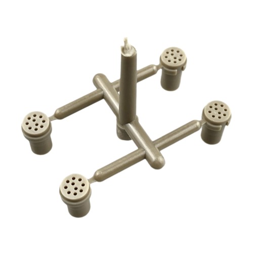
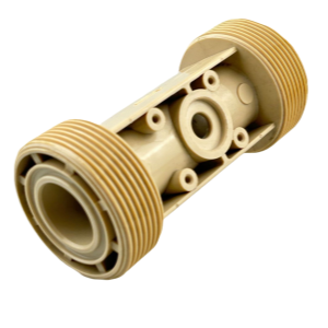
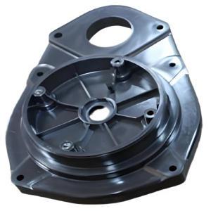
This is a Multi-cavity PEEK molding part. We need to balance fill speed across all branches while also addressing venting issues around the porous areas. Here is a breakdown of how we design the mold:
Specifications
|
Parameter
|
Specification / Description
|
|
Material
|
PEEK (Unfilled / Glass-Filled / Carbon-Filled / Bearing Grade)
|
|
Color
|
Natural / Black / Customizable
|
|
Mold Cavity
|
Multi-Cavity (2 / 4 / 8 / 16 / 32 cavities, up to 64 depending on part size & geometry)
|
|
Tolerance
|
±0.02mm (for critical dimensions, e.g., threads & bore); ±0.05mm for general dimensions
|
|
Continuous Use Temp
|
Up to 250°C (Short-term up to 300°C)
|
|
Shrinkage Rate
|
0.4–0.7% (Unfilled PEEK); 0.2–0.5% (Filled PEEK)
|
|
Surface Finish
|
SPI-A1 Mirror Finish (Internal bore) / SPI-B1 or Texture (External ribs & threads)
|
|
MOQ
|
5,000 – 50,000 pcs (Multi-cavity tooling optimized for high-volume production)
|
|
Lead Time
|
Samples: 25–30 days (Multi-cavity mold trial & validation)
Mass Production: 30–45 days (PEEK requires high mold temps & slow cooling)
|
|
Processing
|
Injection Molding (Requires high mold temp 180–200°C; hot runner system recommended for multi-cavity balance)
|
|
Application
|
Chemical fluid handling / Medical device components / Aerospace connectors / Analytical instrument housings / Automotive under-hood parts / Electrical insulators
|
|
Packing
|
Anti-static bag + EPE foam + Export carton
|
Multi-Cavity PEEK Injection Molding Process Breakdown
1. Mold Design for Multi-Cavity PEEK Tooling
1Balanced Runner System
Multi-cavity PEEK molds demand a fully balanced runner layout to ensure identical fill pressure, melt temperature, and packing across every cavity. An unbalanced system causes cavity-to-cavity dimensional variation — unacceptable for PEEK parts held to ±0.02mm. Hot runner manifolds with individually controlled tips are strongly recommended for 8+ cavity tools, allowing fine-tuning of each cavity's melt delivery without disturbing the others.
2Gate Location Design
We use a center pin gate (submarine gate), and we place it at the top or bottom center of the central cylindrical body.
Why it works: PEEK melt flows radially from the center outward, giving us the shortest and most symmetrical flow paths. This helps keep filling pressure consistent at the ends of all four branches, which reduces warping caused by flow imbalance.
3Special Handling for the "Porous Ends"
Those four ends with all the small holes are difficult for injection molding—they mainly create areas where trapped gas can cause burns or short fills.
Venting comes first: The gate design has to work hand-in-hand with venting. Ideally, the melt should push from the roots of the holes toward the openings, not be trapped inside those tiny holes.
Balanced runners: The connecting bars (runners) between the center and the four ends need to have consistent thickness. If they're too thin, the melt will cool down and won't be able to fill those thin wall sections around the holes. We recommend making the runner diameter at least 0.8 to 1 times the thickest wall section of the part.
4Gate Size and Type Optimization
We select a fan gate or Tab gate, where the melt enters the cylindrical ends and goes with a fan-shaped transition. PEEK has high viscosity; if the injection system has a sudden change in cross-section, it will cause jetting marks. A fan design needs to let the melt spread out smoothly and prevent it from blasting straight into the core pins.
Size control: PEEK solidifies really fast, so gate thickness is usually about 50–70% of the part wall thickness. For precision parts like this, we don't want the gate too small – that creates too much shear heat and can degrade the material (turning it black). But we also don't want it too big; the cooling time drags out, and internal stress increases.
5Draft Angle Design (Multi-Cavity Consistency)
Internal surfaces (core side): PEEK is hard but not super tough, so the inside walls of holes and U-shaped slots need enough draft to eject easily. We recommend at least 1°30' as a minimum — if the depth goes over 20mm, bump it up to 2° or more. Every cavity core must be cut to identical draft; a single under-drafted cavity will cause sticking and cycle interruption.
External surfaces (cavity side): Outside surfaces have less resistance, but we still need at least 1° of draft to keep a nice surface finish and avoid scratches from ejection.
6Polishing and Clearance (Critical for Multi-Cavity)
Mirror finish: PEEK melt has high viscosity and doesn't flow easily, so the core surface really needs an SPI-A1 mirror polish to reduce friction.
Clearance for venting: The gap between ejector pins and the mold plate isn't just for ejection — it's also a key venting path. For PEEK, we recommend cutting venting slots (about 0.01–0.02mm deep) on non-mating surfaces to prevent trapped gas that causes short fills or burning. In multi-cavity tools, venting must be provided for each cavity independently — a shared vent path can favor the cavities closest to the vent, starving the far cavities and causing inconsistent fill. Good venting also helps avoid the vacuum seal, making ejection smoother across all cavities.
2. Injection Process (Multi-Cavity Optimized)
Melt temperature should be set between 360°C and 400°C, with mold temperature maintained at 170°C–200°C to ensure proper crystallization and dimensional stability. In multi-cavity tools, mold temperature uniformity across all cavities is critical — uneven mold temperature causes differential shrinkage and cavity-to-cavity dimension scatter.
Injection pressure generally ranges from 100–140 MPa, while holding pressure is about 60–80% of the injection pressure to minimize shrinkage. In multi-cavity molds, injection pressure must be high enough to fill the farthest cavity while not over-packing the nearest — this is where a balanced runner system and hot runner tip control pay off.
Injection speed should be medium to high to avoid premature freezing, and back pressure is kept low at 0.3–1.0 MPa. Cooling time usually ranges from 30 seconds depending on wall thickness — in multi-cavity tools, cooling time is governed by the thickest section in any cavity, so wall thickness should be as uniform as possible across the part family.
Post-mold annealing at 200°C–250°C for 2–4 hours is typically applied to relieve internal stress and optimize mechanical properties — this step is even more important for multi-cavity production, as it normalizes any residual cavity-to-cavity variation in crystallinity and shrinkage.
3. Why Multi-Cavity for PEEK?
|
Benefit
|
Impact
|
|
Higher output per cycle
|
2–64 parts per shot vs. 1
|
|
Lower unit cost at scale
|
Tooling investment amortized across high volumes
|
|
Consistent quality
|
Balanced runner + uniform cooling = identical parts
|
|
Material savings
|
Hot runner + optimized runners minimize PEEK waste
|
|
Scalable tooling
|
Start 2–4 cavity for validation, scale to 16–32+
|
|
Tight tolerance retention
|
±0.02mm on critical features, cavity-to-cavity
|
|
Ideal for OEM programs
|
Meets high-volume, high-precision PEEK demand
|
4. Applications for Multi-Cavity PEEK Parts
Medical: Surgical instrument components, dental implants, sterilization trays
Aerospace: Connectors, bushings, wear pads, structural clips
Chemical: Pump housings, valve components, fluid handling fittings
Electronics: High-temperature insulators, wafer carriers, connector bodies
Automotive: Transmission seals, bearing cages, under-hood sensors
5. Production Workflow (Multi-Cavity)
1DFM & Moldflow Analysis
Review part design for multi-cavity feasibility. Run Moldflow to predict fill balance, cooling, shrinkage, and warpage. Recommend design changes before cutting steel.
2Multi-Cavity Mold Design & Review
Design balanced runner, uniform cooling, and reliable ejection for every cavity. Specify hot runner, venting, draft angles, and steel. Review and approve 3D mold design.
3Mold Manufacturing
CNC, EDM, and wire cutting to precision. Install hot runner. Polish every cavity to SPI-A1 mirror finish. Cut per-cavity vent slots. Assemble mold.
4Mold Trial & Sample Validation
Mount mold and set PEEK parameters: melt 360–400°C, mold 170–200°C. Collect samples from every cavity. Inspect critical dimensions to ±0.02mm. Compare cavity-to-cavity consistency.
5Process Optimization (Temp, Pressure, Cooling, Balance)
Tune melt/mold temperature, injection/holding pressure, cooling time, and runner balance. Verify all cavities fill simultaneously. Establish process window and calculate Cpk.
6PPAP / First Article Inspection
Full dimensional layout from every cavity. Verify material certs, surface finish, and critical tolerances. Prepare PPAP documentation. Obtain customer approval before mass production.
7Mass Production & Statistical Process Control
Run optimized multi-cavity cycle. Monitor SPC charts for critical dimensions. Anneal parts at 200–250°C for 2–4 hours. Pack in anti-static bags and export cartons.
6. Why Choose Yixing Technology?
120+ Years Experience
Since 2006, we've produced over 1,500 injection molds — with deep expertise in multi-cavity PEEK tooling, balanced hot runner systems, and high-temperature mold design (170–200°C).
2ISO9001 Certificated
Strict quality control with per-cavity dimensional inspection to ±0.02mm, SPC monitoring, and full traceability. ROHS/CE certification available.
3One Stop Service
Complete support from DFM & Moldflow analysis through multi-cavity mold design, SPI-A1 polishing, mold trial, PPAP, annealing, and mass production — one partner, full supply chain.